Druckbasierte und volumenbasierte Strömungskontrolle in der Mikrofluidik

Spritzen- und Peristaltikpumpen gehören seit Jahrzehnten in die biologischen und chemischen Labore. So war es nachvollziehbar, dass diese für den Einsatz in mikrofluidischen Setups bevorzugt wurden. Die beiden Pumpen basieren auf der volumengesteuerten Strömungskontrolle und haben aus hydrodynamischer Sicht eine Reihe von Nachteilen, wodurch deren Einsatz für Mikrosysteme eher ungünstig wird. 

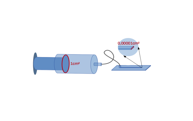
So weisen  Spritzenpumpen erhebliche Limitationen in puncto des verfügbaren Flüssigkeitsvolumens auf. Wird eine Spritze mit einer Querschnittsfläche von A = 1 cm2 an einen typischen Mikrokanal von 10×100μm=0,00001xA angeschlossen, ergibt sich eine 100.000-fache Erhöhung der Strömungsgeschwindigkeit im Mikrokanal. Zwar kann ggf. dieser Nachteil durch den Einsatz von kommerziell verfügbaren hochpräzisen Spritzenpumpen überwunden werden, es bleiben jedoch weitere Schwierigkeiten, beispielsweise das Nachfüllen der Spritze während des Experiments, das gezwungenermaßen hierzu unterbrochen werden muss.

Weitere Infos

In der Peristaltikpumpe erfolgt die Verdrängung des Volumens durch Zusammendrücken des Schlauchs. Das genaue Perfusionsvolumen lässt sich dadurch nur schwer bestimmen, da es vom Schlauchmaterial abhängt, das wiederum in Abhängigkeit von Temperatur und Verschleiß variiert. Auf der Mikroskala führt dieser Ansatz zu einigen Nachteilen. Zudem ist die Strömung pulsierend und Zellen oder andere zu beobachtende Objekte können während des Quetschvorgangs beschädigt werden.

Ein anderer Zugang zur Strömungskontrolle  im mikrofluidischen Kanal basiert auf dem Druck. Am einfachsten erreicht man dies durch die Ausnutzung des hydrostatischen Drucks, wobei 100 mbar 1m Wassersäule entsprechen. Nachteilig ist es jedoch dabei, dass kleinste Luftschwankungen bzw. Änderungen des atmosphärischen Drucks oder Vibrationen das Experiment beeinflussen können. 

Seit 2004 werden in der Mikrofluidik druckbasierte Strömungsregler verwendet. Sie ermöglichen eine ultraschnelle, sanfte, präzise und vibrationsunempfindliche Strömungskontrolle im Mikrokanal. Zudem können Flüssigkeiten nachgefüllt werden, ohne dass das Experiment dabei unterbrochen werden muss. Für diesen Ansatz ist es notwendig, in Druck und nicht in Volumen zu denken, um die Strömung im Mikrokanal zu kontrollieren. Falls erforderlich, kann die Flussrate mit Durchflusssensoren gemessen, berechnet oder kalibriert werden, z. B. durch Abwiegung.

Durchflusssensoren und druckbasierte Strömungskontrolle in der Mikrofluidik

Beim Einsatz der druckbasierten Strömungskontrolle in der Mikrofluidik arbeitet man mit Druck, nicht mit volumetrischen Durchflussraten. In einigen Fällen ist es jedoch notwendig oder von Vorteil, die volumetrische Flussrate im Mikrokanal zu kennen. Beispielsweise bei der Realisierung eines vorgegebenen Protokolls für die Zellkultur, Stöchiometrie im Mikrokanal oder einfach zur Überwachung des Verbrauchs von wertvollen Reagenzien. In solchen Situationen kann die Flussrate im Kanal auf unterschiedlichen Wegen bestimmt werden. In der Regel kann man sie berechnen, indem man die Tröpfchen bei bestimmten Druckwerten wiegt und so das System kalibriert. Dies ist die genaueste Methode, sie ist aber auch etwas umständlich. Eine gute Alternative hierzu sind kommerziell verfügbare Durchflusssensoren.

The available flow meters in the market are usually integrated upstream of the microchannel. However, the measured flow rate is not precisely equivalent to the actual volumetric flow rate, since the method is indirect, e.g. based on the temperature or Coriolis force. It makes the calibration before use mandatory. [/text_output][text_output]

Weitere Infos

Furthermore,  besteht die Notwendigkeit, die Präzision der derzeit angebotenen Sensoren im µl-Bereich um einiges zu optimieren, um zuverlässige Ergebnisse bei der Messung zu erzielen. 

Die Durchflusssensoren für die Mikrofluidik basieren auf unterschiedlichen Ansätzen. Die bekanntesten verwenden zwei Prinzipien:

  • temperaturbasierte Durchflussmessung
  • Durchflussmessung basierend auf der Corioliskraft

Bei der temperaturbasierten Messung wird der Flüssigkeit eine winzige Wärmemenge zugeführt. Die Temperaturdifferenzen, die von vor- und nachgeschalteten Sensoren überwacht werden, geben Auskunft über den tatsächlichen Durchfluss. Dennoch müssen in diesem Fall die physikalischen Eigenschaften der verwendeten Flüssigkeit berücksichtigt werden,  etwa spezifische Wärmekapazität der Flüssigkeit. 

Coriolis-Durchflusssensoren, die in industriellen Anwendungen oft eingesetzt werden, sind auch für die Messung des Massenstroms in der Mikrofluidik verfügbar. Sie basieren in der Regel auf u-förmigen Rohren. Das Prinzip dieser Durchflussmesser basiert auf der Messung der Phasenverschiebung der stetigen Schwingung an verschiedenen Stellen entlang des Rohres, die durch die einströmende Flüssigkeit in das System entsteht. Für Flüssigkeiten mit konstanter Dichte kann der Volumenstrom direkt aus dem gemessenen Massenstrom bestimmt werden. Bei Flüssigkeiten mit variabler Dichte, z. B. im Falle der Kompressibilität, Tröpfchen, Blasen, ist dieser Ansatz mit Schwierigkeiten verbunden. Dieses Verfahren ist zudem generell anfällig gegen externe Vibrationen oder Bewegungen.

Methods of Flow Control

Pressure and flow rate are the main physical parameters which describe flow in microfluidic channels and devices. They are not independent from each other, but related through the flow resistance depending on the channel design and fluid properties quite similar to voltage and current in electrical circuits. 

Pressure is defined as force per area and we distinguish hydraulic and pneumatic pressure. These quantities are studied in the fields of Hydraulics and Pneumatics and all together in Hydrodynamics. Hydraulic pressure describes the exerted pressure transmitted by an incompressible medium as a liquid onto an immersed object or a boundary, e. g. water on biological cells or oil phase droplets in multi-phase fluids.

Weitere Infos

Pneumatic pressure, on the other hand, exerts force by means of a compressible medium, e. g. air, on an object or a boundary. Compressible media act like a spring and can store energy. This energy can be recuperated later allowing for smoothing out unwanted pressure pulses.  Pneumatic pressure can be transformed into hydraulic pressure by using a free water-air interface in a closed vessel carrying over the energy storage property to the liquid.

Displacement of liquids and gases can be realised by essentially two approaches: volume-driven or pressure driven flow. They rely on the properties of the conjugated quantities “pressure” and “volume” as known from thermodynamics. Both methods have very different characteristics – especially scaling – and one can choose one of them to control fluids.

Volume-driven control relies on the volume as a means of fluid movement control, requiring a closed and leakage-free system. They are best realised with liquids, since liquids essentially keep their volume mostly independent of pressure (incompressible). In microfluidics water and oil are the most common representatives. Pressure is generated by piston displacement in a syringe and exerted onto a downstream channel system which has to be tightly closed with exception of the waste outlet, of course. Here, pressure is not controlled and often not monitored. The scaling of this approach is poor, e. g. a minute piston displacement can result in a very large (up to 6 orders)  increase in hydraulic pressure in an attached microfluidic device. Further elasticity in the tubing and materials, leaks or air bubbles may reduce considerably responsiveness degrading device reliability and safety. In larger hydraulic systems sudden changes in volume flow may result in large pressure shocks (“hydraulic surge” or “water hammer”) or create strong shear forces damaging sensitive parts of devices, such as valves and small microfluidic structures or embedded objects like biological cells.

Pressure-driven control, on the other hand, is best realised with compressible gasses, such as air or inert gasses as nitrogen. Pneumatic pressure is typically generated by a pressure and/or vacuum control system fuelling a pressure storage recipient. The pressurised gas can subsequently drive liquid flow in microfluidic devices by connecting them to the liquid in the storage recipient. Sudden changes in flow rates will not cause pressure spikes, even if the gas source delivers pulsating pressure, since gas absorbs excessive forces and pulses by means of it’s compressibility. As the liquid in the recipient is in contact to gas atmosphere, the system is not anymore closed as beforehand. Therefore pressure driven systems are usually “open systems”. The displaced volume is not controlled and often not monitored. As pneumatic-driven systems do not get in direct contact with the handling fluid any kind of contamination  is prevented and subsequent cleaning of the device is unnecessary. It is advantageous that back pressure is absorbed by gas compression and quickly eliminated by pressure stabilisation. By design, pressure-driven systems hence are more reliable, safer and require minimal maintenance. Thus, pneumatic pressure-driven systems are ideal for microfluidic channels and devices.

Pneumatischer und hydrostatischer Druck

Unsere Atmosphäre übt Druck auf alle Oberflächen aus. Flüssigkeiten können dies ebenfalls tun. Im Falle der Atmosphäre drückt das Gewicht des gesamten Gases oben aufgrund der Schwerkraft nach unten und erzeugt einen isotropen Druck, der auf Meereshöhe eine ziemlich beeindruckende Größenordnung erreichen kann, die ungefähr dem Druck einer Masse von 1 kg auf 1 cm2entspricht. Flüssigkeiten haben jedoch eine viel höhere Dichte als Luft, etwa das 1000-fache, und mit der Tiefe steigt der Druck viel schneller an. Der Druck einer Flüssigkeit in Abhängigkeit von deren Gewicht wird als hydrostatischer Druck bezeichnet.

Veranschaulichen wir das Ganze anhand eines Zylinders (oder einer anderen Form) auf einer ebenen Fläche Z. Der Zylinder mit einer bestimmten Masse und Gravitationskraft F übt einen Druck p auf die untere Grenzfläche mit gegebener Fläche aus: p=F / A. Dies gilt für feste, flüssige und gasförmige Stoffe gleichermaßen. Ersetzt man den Kraftterm mit den Materialeigenschaften einer Flüssigkeit, z. B. Wasser, und den geometrischen Eigenschaften des hypothetischen Zylinders, so ergibt sich ein hydrostatischer Druck von p = h ·ρ · g,, wobei h Höhe der Flüssigkeitssäule ist,  ρ (“rho”) the liquid density and g the gravitational acceleration. Thus, the hydrostatic pressure does not depend on the size of the cross-sectional area of the liquid column, but only on the height of the liquid column and the density of the liquid. In fact, the hydrostatic pressure is also indifferent to the shape of the hypothetical column.

Weitere Infos

When working with pressure-driven microfluidic systems, the hydrostatic pressure should always be considered, no matter how small the liquid quantities are. For instance, a one-meter-high water column is already generating a hydrostatic pressure of approx. 10 kPa, or 100 mbars, being quite significant in Microfluidics. Thus, when driving fluids through microfluidic devices, the liquid levels in microfluidic devices can vary considerably in height which is often neglected. Liquid reservoirs of tall and narrow shape appear to be especially prone to systematic pressure deviations. Other common sources of experiment errors are long microfluidic tubings transferring fluids upwards and downwards and even worse if still being partially filled with air. Here, the applied pressure at the source may deviate strongly from the received pressure at the microfluidic device. Once all tubings are filled with liquid and the micro-channel is placed approx. at the same height as the reservoirs and tubings are reduced to minimum, this phenomenon reduces strongly. How to explain this?

Responsible for this is the “hydrostatic drift”. It can be understood and calculated as follows: 

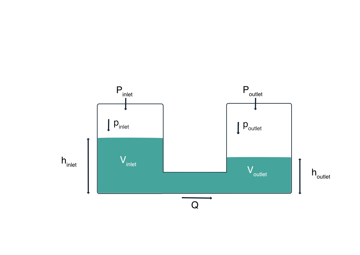
The flow rate Q is proportional to the applied pressure (P) difference plus the hydrostatic pressure (p) difference: 

Q ∼ Δ P = Pinlet – Poutlet + pinlet – poutlet

The flow resistance R determines the resulting flow rate: 

Q = 1/R · Δ P

Flowing liquid changes the liquid levels in the outlet-reservoir with liquid volume Voutlet(t): 

dVoutlet(t) ⁄ dt = Q(t)

With constant reservoir cross section Z, note that Vinlet(t) + Voutlet(t) , hinlet(t) + houtlet(t) and also pinlet(t) + poutlet(t) remain constant, if the total amount of liquid remains unchanged during this experiment. 

Hence, the level in the reservoirs changes with volume Voutlet(t) = A ·houtlet(t) accordingly:

dVoutlet(t) ⁄ dt = A · (dhoutlet(t)/dt) = 1/R · Δ P(t) = 1/R (Pinlet – Poutlet) + 1/R (pinlet(t) – poutlet(t))

Hence:  

A / (ρ · g) · (dpoutlet(t)/dt) = 1/R (Pinlet-Poutlet) + 1/R (pinlet(t)-2poutlet(t))

which is an inhomogeneous ordinary differential equation of 1st order with an exponential solution rising or decaying with the time scale (A · R) / (2ρ · g). 

We conclude that less tall reservoirs of larger cross section, or higher hydrodynamic flow-channel resistances reduce the hydrostatic drift. 

If the flow rate should remain constant over a long period of time, hydrostatic drift compensation is recommended: The applied pressures have to be conducted such that the right side of the differential equation remains constant. The P2CS has a build-in function to accomplish this compensation automatically, with the function-setup: 

set:hystatic_pressure 

set:hystatic_pressure:timescale

On the other hand, the hydrostatic pressure can also be useful as an excellent source of (quasi-)static pressure for experimental setups. As illustrated, a one-meter large water column can generate significant pressures at the lower end. When doing experiments which require constant pressures with minimal liquid transfer (such that the liquid level of the column will not significantly decrease), water columns present an excellent and inexpensive tool for microfluidic and mesofluidic applications.

Authors: Fütterer, C., Kubitschke, H., Prasol, K.

[text_output]Melden Sie sich zu unserem Newsletter an!

We regularly update this page with new technical and application notes as well as background information on Microfluidics, Hydrodynamics and more. If you want to stay updated, please subscribe.[/text_output]
[newsletter_form]