Pressure-driven and Volume-driven Flow Control in Microfluidics

Since decades syringe and peristaltic pumps belong to biological and chemical laboratories. Thus, it was comprehensible that they were the first choice for the use with microfluidic devices, i.e. at a microscale. Still, in the hydrodynamical view both instruments for the volume-driven flow control have a number of bottlenecks which make them not favourable for the use at a microscale. 

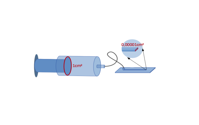
For instance,  syringe pumps have considerable limits on the side of the liquid column. If a syringe with a cross-sectional area of A = 1 cm2 is connected to a typical microchannel of 10×100μm=0.00001xA cross-section, this results in a 100,000-fold amplification of the flow velocity in the microchannel. Probably, this disadvantage can be overcome by usage of highly precise syringe pumps in the market, but still there will be more difficulties, such as refilling the volume during the experiment, which has necessarily to be interrupted for it.

More...

In the peristaltic pump the volume is displaced by peristaltic tube squeezing.  This makes it difficult to determine the exact perfusion volume, since it is dependent on the tube material, which again varies depending on the temperature and wear. This approach is  associated with some difficulties at a microscale. Furthermore, the flow is pulsating and cells or other objects under observation can be damaged during the squeezing process. 

Another way to control the flow in  the microfluidic channel is to use the pressure. The easiest way is the hydrostatic pressure whereas 100 mbar correspond to 1 m water column. Still, minor air fluctuations or changes of the atmospheric pressure or vibrations will impact the experiment. 

Starting in 2004, pressure-driven flow controllers are used in Microfluidics. They allow to control the flow in a microchannel very fast, gently, precisely and not prone to vibrations. Also refilling of fluids without interrupting the experiments is possible. For this approach it is necessary to think in pressure, not in volume in order to control the flow in the microchannel. The flow rate can then be determined with flow meters, calculated or calibrated, e.g. by weighing.

Flow Meters and Pressure-driven Flow Control in Microfluidics

When working with pressure-driven flow control systems in Microfluidics, we are working with pressure, not with volumetric flow rates. However, in some cases it is necessary or helpful to know the volumetric flow rate of the fluid in the microchannel. For example, in order to follow a specific protocol for a cell culture, stoichiometry in the microchannel or just to monitor the consumption of precious reagents. In such cases there are different approaches to determine the flow rate in the channel. In general, you can calculate it by weighing the droplets at specific pressure values and thus calibrate the system. This is the most precise method, however, cumbersome. Or you can use commercially available flow meters.

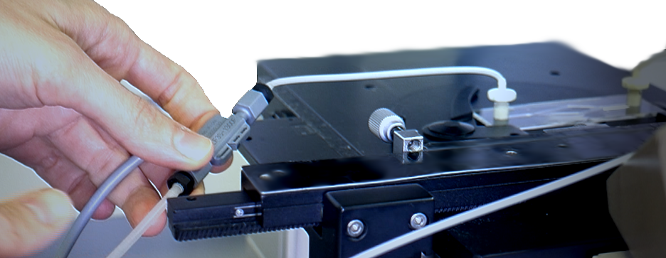
The available flow meters in the market are usually integrated upstream of the microchannel. However, the measured flow rate is not precisely equivalent to the actual volumetric flow rate, since the method is indirect, e.g. based on the temperature or Coriolis force. It makes the calibration before use mandatory.

More...

Furthermore,  the accuracy of the currently available flow meters in the µl range has to be optimised significantly in order to obtain reliable results. 

The liquid flow meters for the Microfluidics use different approaches. The most known ones use two principles:

  • temperature-based flow measurement
  • Coriolis force-based flow measurement

For the temperature-based measurement a tiny amount of heat is introduced to the fluid. The temperature differentials, which are monitored by sensors up- and downstream, provide information on the actual flow. Still, in this case you have to consider the physical properties of the used fluid,  e.g. specific heat capacity of the fluid. 

Coriolis flow meters, which are widely used in industry, are also available for the mass flow measurement in Microfluidics. They usually are based on u-shaped pipes. The principle of these flow meters is based on the measurement of the phase shift of the steady vibration at different locations along the pipe, which, however, emerges through the incoming fluid into the system. For constant density fluids, the volumetric flow rate can be directly determined from the measured mass flow rate of the sensor. However, this approach is difficult for fluids with variable density, e.g. compressibility, droplets, bubbles, and is prone to external vibrations or movements.

Methods of Flow Control

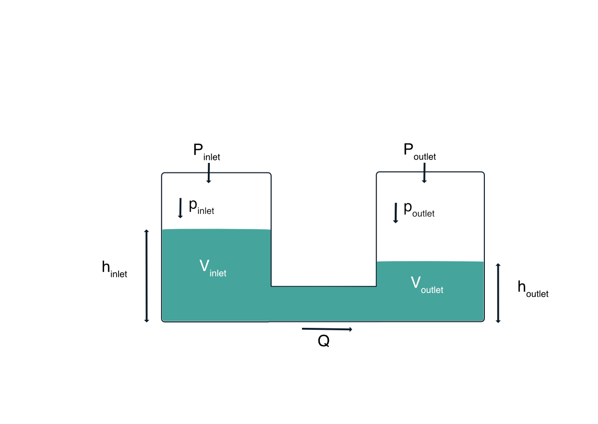
Pressure and flow rate are the main physical parameters which describe flow in microfluidic channels and devices. They are not independent from each other, but related through the flow resistance depending on the channel design and fluid properties quite similar to voltage and current in electrical circuits. 

Pressure is defined as force per area and we distinguish hydraulic and pneumatic pressure. These quantities are studied in the fields of Hydraulics and Pneumatics and all together in Hydrodynamics. Hydraulic pressure describes the exerted pressure transmitted by an incompressible medium as a liquid onto an immersed object or a boundary, e. g. water on biological cells or oil phase droplets in multi-phase fluids.

More...

Pneumatic pressure, on the other hand, exerts force by means of a compressible medium, e. g. air, on an object or a boundary. Compressible media act like a spring and can store energy. This energy can be recuperated later allowing for smoothing out unwanted pressure pulses.  Pneumatic pressure can be transformed into hydraulic pressure by using a free water-air interface in a closed vessel carrying over the energy storage property to the liquid.

Displacement of liquids and gases can be realised by essentially two approaches: volume-driven or pressure driven flow. They rely on the properties of the conjugated quantities “pressure” and “volume” as known from thermodynamics. Both methods have very different characteristics – especially scaling – and one can choose one of them to control fluids.

Volume-driven control relies on the volume as a means of fluid movement control, requiring a closed and leakage-free system. They are best realised with liquids, since liquids essentially keep their volume mostly independent of pressure (incompressible). In microfluidics water and oil are the most common representatives. Pressure is generated by piston displacement in a syringe and exerted onto a downstream channel system which has to be tightly closed with exception of the waste outlet, of course. Here, pressure is not controlled and often not monitored. The scaling of this approach is poor, e. g. a minute piston displacement can result in a very large (up to 6 orders)  increase in hydraulic pressure in an attached microfluidic device. Further elasticity in the tubing and materials, leaks or air bubbles may reduce considerably responsiveness degrading device reliability and safety. In larger hydraulic systems sudden changes in volume flow may result in large pressure shocks (“hydraulic surge” or “water hammer”) or create strong shear forces damaging sensitive parts of devices, such as valves and small microfluidic structures or embedded objects like biological cells.

Pressure-driven control, on the other hand, is best realised with compressible gasses, such as air or inert gasses as nitrogen. Pneumatic pressure is typically generated by a pressure and/or vacuum control system fuelling a pressure storage recipient. The pressurised gas can subsequently drive liquid flow in microfluidic devices by connecting them to the liquid in the storage recipient. Sudden changes in flow rates will not cause pressure spikes, even if the gas source delivers pulsating pressure, since gas absorbs excessive forces and pulses by means of it’s compressibility. As the liquid in the recipient is in contact to gas atmosphere, the system is not anymore closed as beforehand. Therefore pressure driven systems are usually “open systems”. The displaced volume is not controlled and often not monitored. As pneumatic-driven systems do not get in direct contact with the handling fluid any kind of contamination  is prevented and subsequent cleaning of the device is unnecessary. It is advantageous that back pressure is absorbed by gas compression and quickly eliminated by pressure stabilisation. By design, pressure-driven systems hence are more reliable, safer and require minimal maintenance. Thus, pneumatic pressure-driven systems are ideal for microfluidic channels and devices.

Hydrostatic and Pneumatic Pressure

Our atmosphere applies pressure on all surfaces, liquids can also do so. In case of the atmosphere the weight of the entire gas above is pushing downwards due to gravity creating an isotropic pressure to generate a quite impressive pressure at sea level equivalent to approx. a mass of 1 kg pushing on 1 cm2. Liquids, however, have a much higher density than air, approx. 1000-fold, and a much more rapid pressure raise with depth is fact. The pressure of a liquid due to its weight is termed hydrostatic pressure.

The physical origin can be illustrated by a cylinder (or any other shape) placed on a flat surface A. The cylinder with a certain mass and gravitational force F will apply a pressure p onto the bottom interface with given area: p=F / A. This holds true for solid, liquid and gaseous matter as well. When substituting the force term with the material properties of a liquid, e.g. water, and the geometric properties of the hypothetical cylinder, the hydrostatic pressure will be p = h ·ρ · g, whereas h is the height of the liquid column, ρ (“rho”) the liquid density and g the gravitational acceleration. Thus, the hydrostatic pressure does not depend on the size of the cross-sectional area of the liquid column, but only on the height of the liquid column and the density of the liquid. In fact, the hydrostatic pressure is also indifferent to the shape of the hypothetical column.

More...

When working with pressure-driven microfluidic systems, the hydrostatic pressure should always be considered, no matter how small the liquid quantities are. For instance, a one-meter-high water column is already generating a hydrostatic pressure of approx. 10 kPa, or 100 mbars, being quite significant in Microfluidics. Thus, when driving fluids through microfluidic devices, the liquid levels in microfluidic devices can vary considerably in height which is often neglected. Liquid reservoirs of tall and narrow shape appear to be especially prone to systematic pressure deviations. Other common sources of experiment errors are long microfluidic tubings transferring fluids upwards and downwards and even worse if still being partially filled with air. Here, the applied pressure at the source may deviate strongly from the received pressure at the microfluidic device. Once all tubings are filled with liquid and the micro-channel is placed approx. at the same height as the reservoirs and tubings are reduced to minimum, this phenomenon reduces strongly. How to explain this?

Responsible for this is the “hydrostatic drift”. It can be understood and calculated as follows: 

The flow rate Q is proportional to the applied pressure (P) difference plus the hydrostatic pressure (p) difference: 

Q ∼ Δ P = Pinlet – Poutlet + pinlet – poutlet

The flow resistance R determines the resulting flow rate: 

Q = 1/R · Δ P

Flowing liquid changes the liquid levels in the outlet-reservoir with liquid volume Voutlet(t): 

dVoutlet(t) ⁄ dt = Q(t)

With constant reservoir cross section A, note that Vinlet(t) + Voutlet(t) , hinlet(t) + houtlet(t) and also pinlet(t) + poutlet(t) remain constant, if the total amount of liquid remains unchanged during this experiment. 

Hence, the level in the reservoirs changes with volume Voutlet(t) = A ·houtlet(t) accordingly:

dVoutlet(t) ⁄ dt = A · (dhoutlet(t)/dt) = 1/R · Δ P(t) = 1/R (Pinlet – Poutlet) + 1/R (pinlet(t) – poutlet(t))

Hence:  

A / (ρ · g) · (dpoutlet(t)/dt) = 1/R (Pinlet-Poutlet) + 1/R (pinlet(t)-2poutlet(t))

which is an inhomogeneous ordinary differential equation of 1st order with an exponential solution rising or decaying with the time scale (A · R) / (2ρ · g). 

We conclude that less tall reservoirs of larger cross section, or higher hydrodynamic flow-channel resistances reduce the hydrostatic drift. 

If the flow rate should remain constant over a long period of time, hydrostatic drift compensation is recommended: The applied pressures have to be conducted such that the right side of the differential equation remains constant. The P2CS has a build-in function to accomplish this compensation automatically, with the function-setup: 

set:hystatic_pressure 

set:hystatic_pressure:timescale

On the other hand, the hydrostatic pressure can also be useful as an excellent source of (quasi-)static pressure for experimental setups. As illustrated, a one-meter large water column can generate significant pressures at the lower end. When doing experiments which require constant pressures with minimal liquid transfer (such that the liquid level of the column will not significantly decrease), water columns present an excellent and inexpensive tool for microfluidic and mesofluidic applications.

Authors: Fütterer, C., Kubitschke, H., Prasol, K.

Newsletter Subscription

We regularly update this page with new technical and application notes as well as background information on Microfluidics, Hydrodynamics and more. If you want to stay updated, please subscribe.